A skyloop antenna is a loop of wire held up in the sky. A 160m antenna is tuned for top band. A balanced feeder drives one point of the loop, and the signal propagates in both directions from the feeder point, forming a standing wave when the travel time around the loop is equal to the cycle time of the driving signal. That means that a 160m skyloop should be a little bit shorter than 160 metres, because wire slows the propagation speed to a teeny bit less than the speed of light.
A standing wave is also formed when the travel time is twice the cycle time of the driving signal, and another when it is three times, and so on. This means that a 160m skyloop should tune at 160m, at 80m, at 53.3m, at 40m, at 32m, at 26.7m, and so on. With careful choice of the basic tuning frequency the entire HF bandplan can be covered.
| Harmonic | Resonant frequency | band | In-Band? |
|---|---|---|---|
| Fundamental | 1780kHz | 160m (1810kHz - 2000kHz*) | 30kHz/1.7% below |
| 2nd | 3560kHz | 80m (3500kHz - 3800kHz) | yes |
| 3rd | 5340kHz | 60m (5000kHz - 5500kHz) | yes |
| 4th | 7120kHz | 40m (7000kHz - 7200kHz**) | yes |
| 6th | 10680kHz | 30m (10100kHz - 10150kHz) | 530kHz/5% above |
| 8th | 14240kHz | 20m (14000kHz - 14350kHz) | yes |
| 10th | 17800kHz | 17m (18068kHz - 18168kHz) | 200kHz/1.5% below |
| 12th | 21360kHz | 15m (21000kHz - 21450kHz) | yes |
| 14th | 24920kHz | 12m (24890kHz - 24990kHz) | yes |
| 16th | 28480kHz | 10m (28000kHz - 29700kHz) | yes |
|
*In Ireland, top-band transmission above 1850kHz is limited to 10W, which makes it much less useful. | |||
|
**Range in Ireland | |||
However, this broad coverage comes at a cost. At the fundamental frequency the transmission pattern is unidirectional, but at the first harmonic it is bidirectional, like a dipole. (Which means I get better 80m reception to the East and West, since my loop is fed at the North.) For three harmonics there are three directions with strong signal and, as the harmonic number goes up, the antenna pattern starts to look like a sea urchin, with lobes sticking out in every direction. But, once there are enough lobes, it's more or less unidirectional again.
Construction of a skyloop is about measuring a loop of wire and putting it in the air, selecting/constructing an appropriate balun, and running the feeder into the shack.
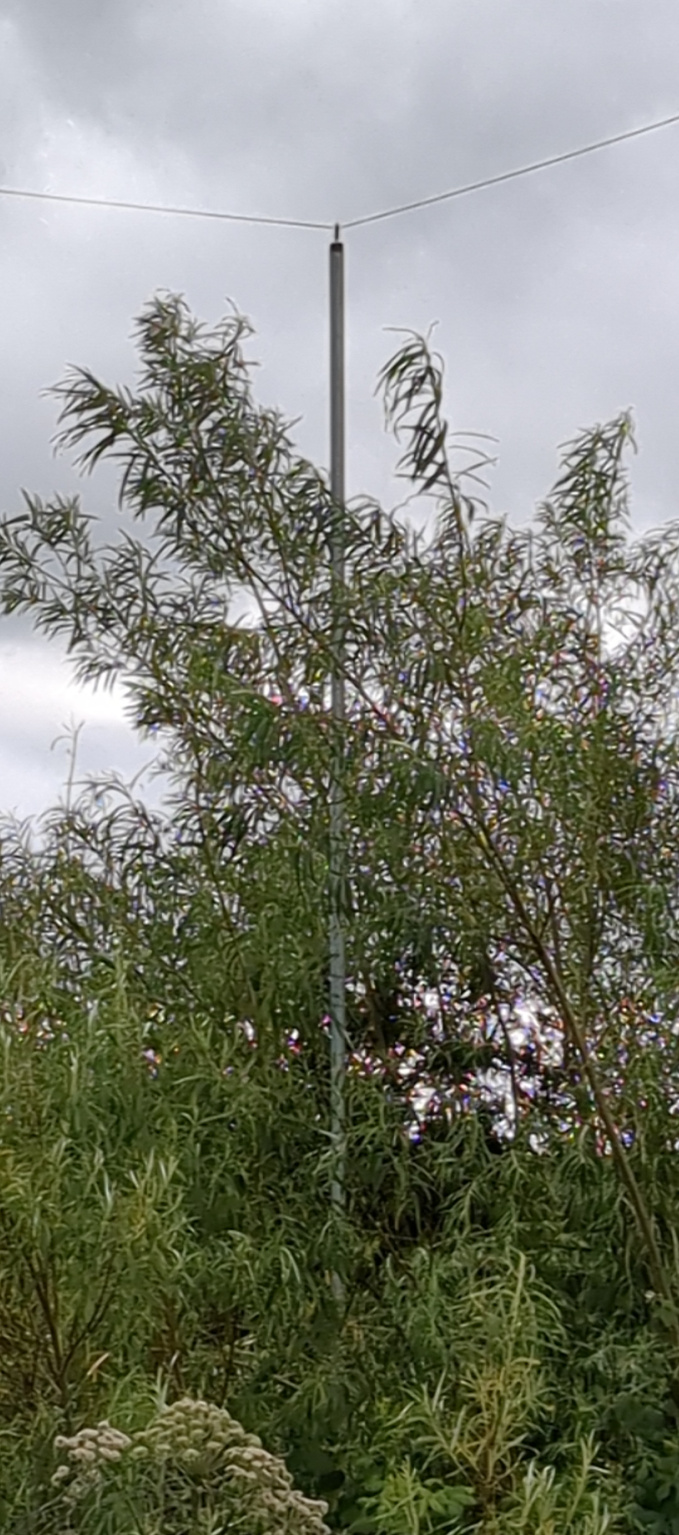
The loop of wire should really be horizontal and a long way in the air. My shack is on the top of a hill, though, and the only available site for the loop has quite a steep drop-off of maybe 10 metres or so. Although the poles for the bottom two corners of the loop are six metre (about 20') galvanised poles with an electric fence insulator attached at the top, the poles at the top of the hill are 3.2 metre (about 11') wooden poles (also with an electric fence insulator.) One corner of the loop is an electric fence insulator screwed into the side of my garage. The shape of the overall loop is sort of trapezoid — certainly not the ideal circle — and is about 70 metres on the longest side but only 50 metres on the shortest width.
Initially I used a lawnmower signal wire since it was cheap, but it did not survive the storms, and needed to be replaced within months. I replaced it with DX-Wire UL Litze: I paid about €80 for a 170m reel. That has now survived its first winter without any apparent fraying or damage.
One pole in the middle of the northern run has the feeder point. The wire is terminated into a window-line that runs down the wooden post, with the balun at the bottom. The balun has to reduce the 600Ω impedance of the loop to the 50Ω impedance of the feeder and radio. Cheap bell wire was wrapped around a Fair-Rite FT-140-43 ferrite toroid. There are 14 turns of bell wire, with one end of the bell wire common, connected to the shield of the feeder. The centre of the feeder is connected to one side of the bell wire after six turns. This gives an effective impedance transformer of 540Ω balanced out for 50Ω in. I run it with 100W apparently without any problems.
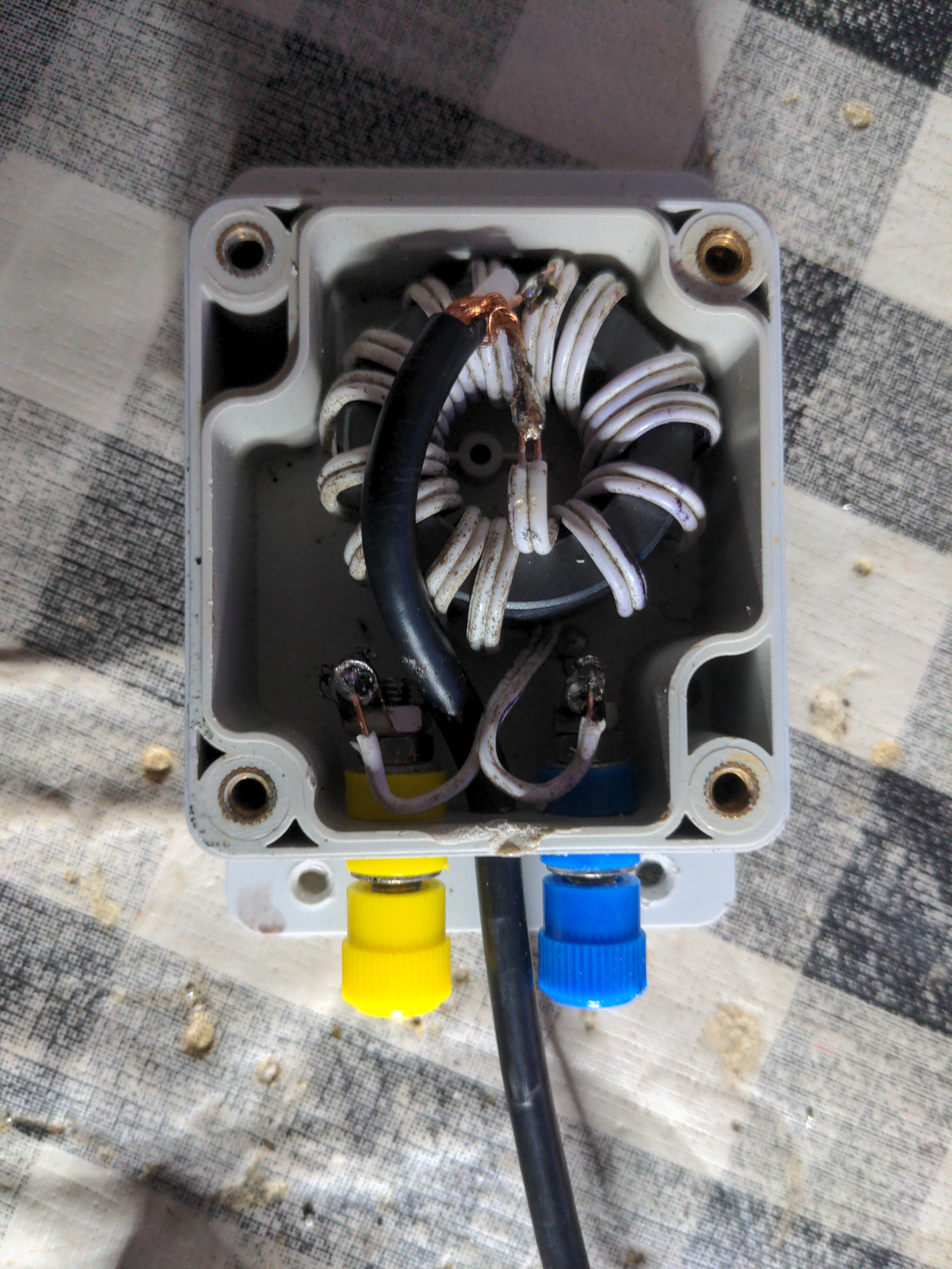
(Please excuse the grubby state of the balun — weatherproofing in Ireland is hard!)
The balun is assembled inside a waterproof plastic box with the connections at the bottom face, as we get a lot of rain in the west of Ireland. The feeder passes through a lightning suppressor which is connected to the spike at the bottom of the post. This complies with the earthing (grounding) system used in my shack here in Ireland, but may not comply with the earthing system in your shack. If you have any doubt at all about earthing, consult a local electrician — don't rely for safety on something you read on the Internet!
Hooking the antenna up to a NanoVNA shows the expected pattern: a series of dips of SWR corresponding to each harmonic of the loop length. The dips are different partly because of the resolution of the NanoVNA screen, but mostly because the loop is not a perfect circle.
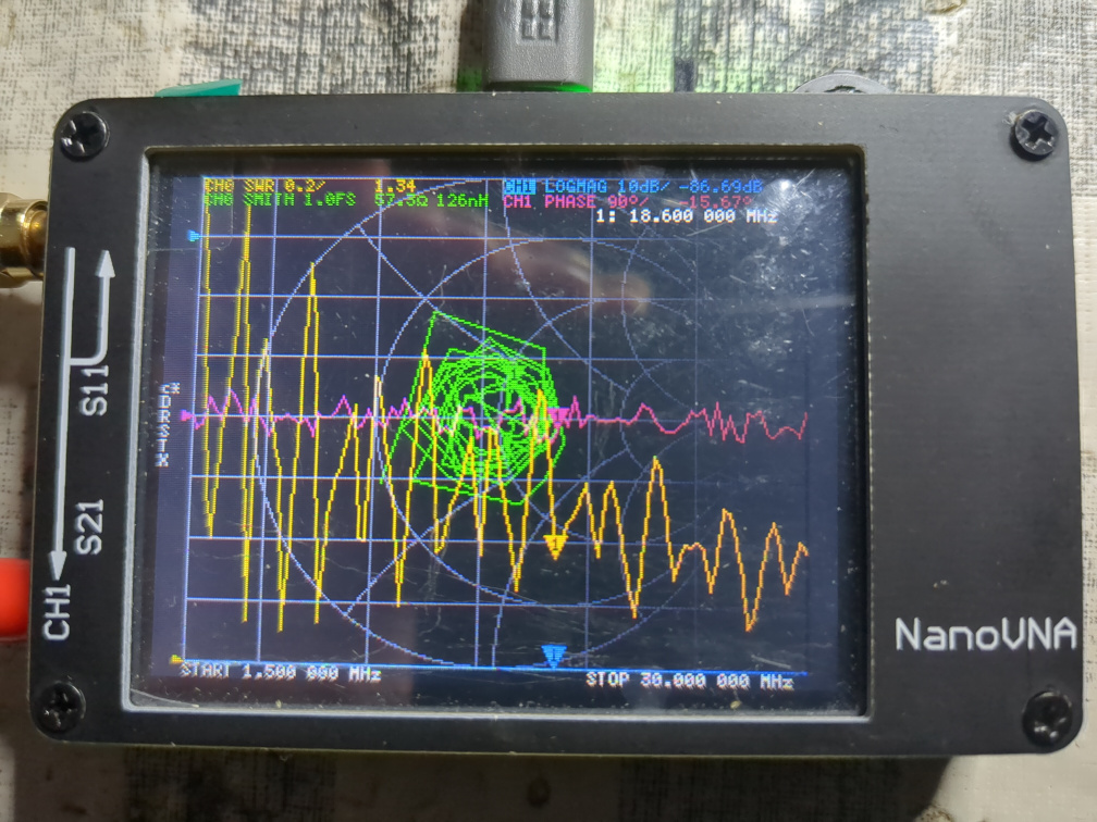
Although the dips do not precisely correspond to the bands, in practice the antenna tuner can tune all the HF bands, as well as (obviously) top-band.
The proof, of course, is reception reports. Unfortunately there was a significant solar storm this weekend, and the bands are not in a good way. Nevertheless a quick go-around with FT8 got some good reception maps from PSK Reporter -- and a few QSOs -- even during the day with the poor MUF we are experiencing right now!
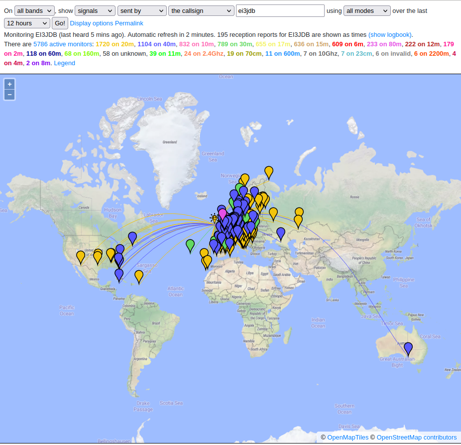
As you can see, I can be heard on five continents. In better band conditions I have made SSB calls as far away as Australia with 100W. I am very happy with my skyloop. If you have space for one, I'd certainly recommend it!
 RSS feed